Inside the Worthington Tower
The Worthington Interlocking Tower was a two story building.
The first floor held equipment most notably the hardware for the switch
levers. The switch levers were connect to the switches themselves by
pipes that rested on rollers so they could move. The pipes came down
from the second floor, made a 90 degree change in direction and left the
building. When they got to the track they made another change in
direction and ran along the track to the switch or signal it controlled.
Each turn required a bell crank to change the direction of travel.

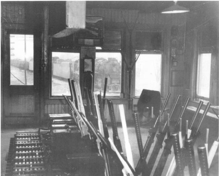
This photo looking south gives an
excellent view of the switch levers.
The levers controlling the switches and
signals had to be changed in a specific sequence. There was a system
of slide bars that kept a lever from being changed out of sequence.
Close to the floor on the left are the
slide bars that made up the interlocking system. Pulling the levers in the
correct sequence slides the bar to unlock the next lever.
For example you couldn’t set the semaphore to clear or caution until the
lever controlling the derail was in the proper position. The derail
couldn’t be closed unless the diamond was lined up properly. The
diamond couldn’t be changed unless the signal and derail were in the proper
position for the track being crossed. That is why these towers were called
interlocking towers, they were designed to eliminate human error as much
as possible.
The levers were either pulled or pushed to switch the track or change a
signal. The handle had a release on it that lifted a locking pin. To
operate the lever you pulled the release to unlock the pin moved the lever
a little, released the lever to the locking pin and moved the lever until
the pin dropped in the hole locking the lever in its new position and
letting the operator know the operation was complete. Only the two PRR
semaphore levers had three positions – stop, approach and proceed. All
other levers controlled switches or derails and had two positions – open
or closed. The signals for the NYC were electronically controlled as
was the NYC passing siding.
On the wall is the
much coveted PRR calendar for 1956. Also on the wall are the train
order hoops used for passing train orders to the engineer and conductor
of a moving train. One of the scariest aspects of an operator's job.
The train order was tied to a loop of string that was stretched and
attached to the order hoop at three points making a triangle. The
operator held the hoop over his head next to the track. The trainman
would put his arm through the triangle of string pulling the string and
train order off the hoop. It took nerves of steel to hold that hoop
while a train not slowing down came at the operator.
Photo by Dave Bunge.

The operator is facing west in this
photo taken in the winter of 1937-38. The telegraph sounder is in the
open wooden box to the left. The wooden box acted as an amplifier
which made it easier to
distinguish the dashes from the dots. A novice would strain
to pick out the individual letters in the message while an experience
telegrapher heard whole words. A super expert would listen to the
message then walk over to his typewriter and type out the message.
By 1937 the operators also had access to
the company phone line. The switch box to the right of the operator
was used to select the line on which he wanted to talk or send a telegraph
message. The
operator has his train sheet on the desk. He would record every
train movement on the daily train sheet.
Photo by Don O'Brien

Another view of the
switch levers this time looking north. You can see another telephone
and the operator's typewriter. Looking out the window the double-tracked Sandusky
Branch is on the left and the Big Four is on the right.
The window glass must
have been very old as it had the waviness characteristic of old glass. Maybe some of the glass in this tower was
reused from the original tower.
Photo by Don O'Brien
Previous ***
Next


